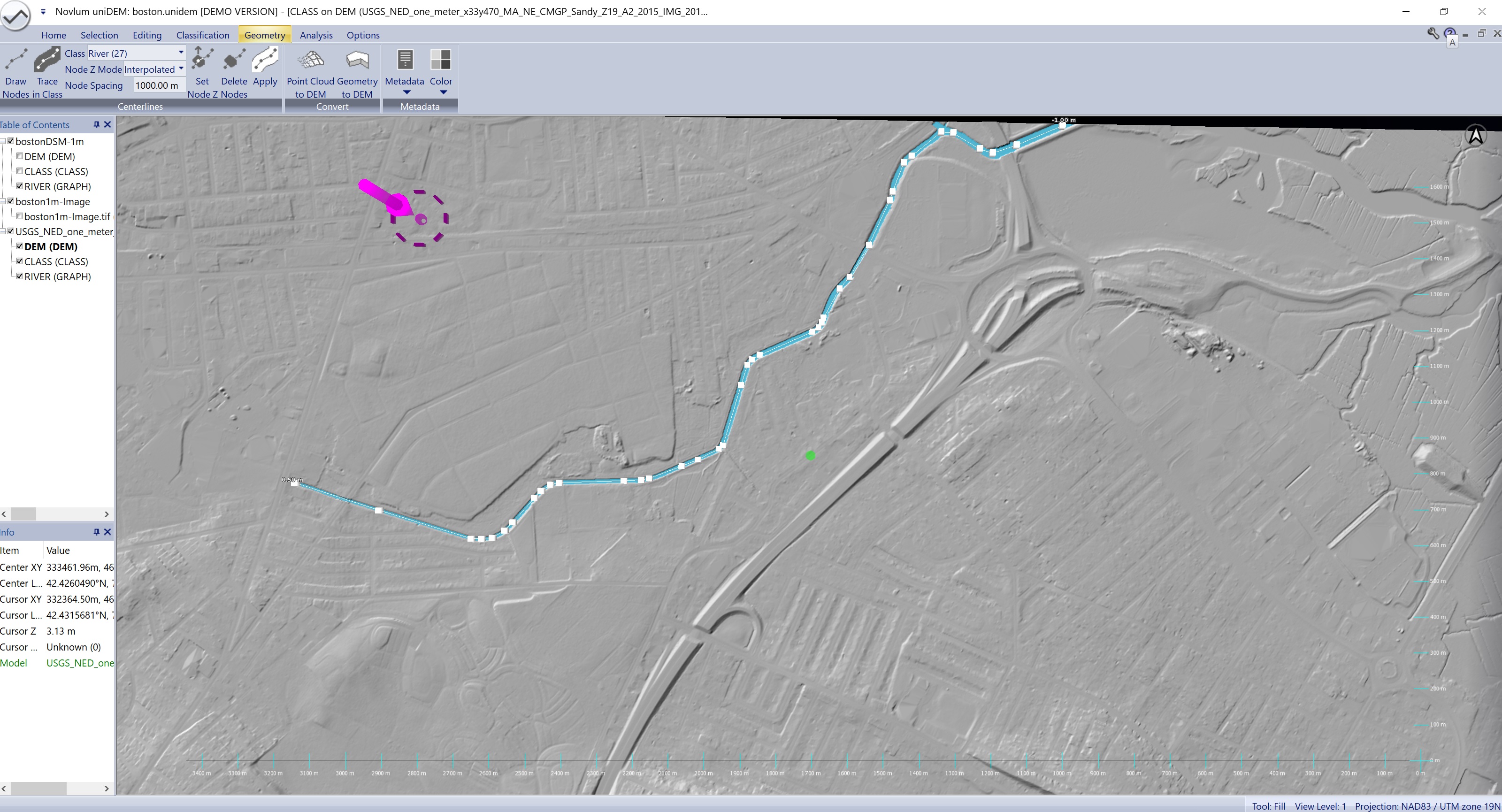
uniDEM supports the delineation of vector centerlines. These are helpful during editing features like rivers, roads, streams and adding breaklines or constructing features. Centerline delineation can be performed manually (Draw Nodes) or in a semi-automated manner (Trace in Class).
Geometries are collected and can be applied to different classifications as selected in the Class dropdown. When Draw Nodes or Trace in Class are active the views are drawn partially transparent. This allows nodes (vertices) to be drawn above and below the terrain as needed to better model the underlying terrain.
Town Line Brook Canal, Massachusetts, US
Selects the Geometry tool for drawing centerlines and creates a new layer of the selected class type if one does not yet exist.
When activated the views will be rendered with transparency so nodes and lines added beneath the terrain can be viewed.
Geometry vectors are collected by holding Shift+Left-Click where each node (vertex) is to be placed. Added nodes exist in three dimensions and are used to delineate the center of a classified feature or to quickly flatten linear features of a fixed width.
Nodes can be one of three types based on the selected Node Z Mode.
The horizontal location of a node can be modified by:
The elevation of a node can be modified by:
Geometries are not just single line vectors but can be used to draw a network topology of intersecting vectors. To connect one vector to another hold Shift+Right-Click over the target node and select Connect.
Default shortcut: none
Geometry delineation of complex classifications can be automated using the Trace in Class feature. This tool uses a cost function to place a centerline between two points that are connected with a single classification.
To create a centerline for a river:
Default shortcut: none
The Class dropdown defines which classification will be used by Trace in Class and Apply.
Default shortcut: none
When drawing a Geometry points between the start and end of a vector can be set to one of the following options:
At any time, the Node Z Mode can be modified by:
Default shortcut: none
Defines the maximum spacing that can occur between two nodes when using the Trace In Class tool. Added nodes will be minimized by spacing them apart when creating the centerline, but will not be simplified below this threshold.
Default shortcut: none
All nodes in a selected area can be set to a defined elevation.
Default shortcut: none
All nodes intersecting with a selection area are deleted.
Default shortcut: none
Flattens a selected area using a defined centerline using either a prescribed width or a classification. For best results Apply to DEM should be used with a classification.
Default shortcut: none
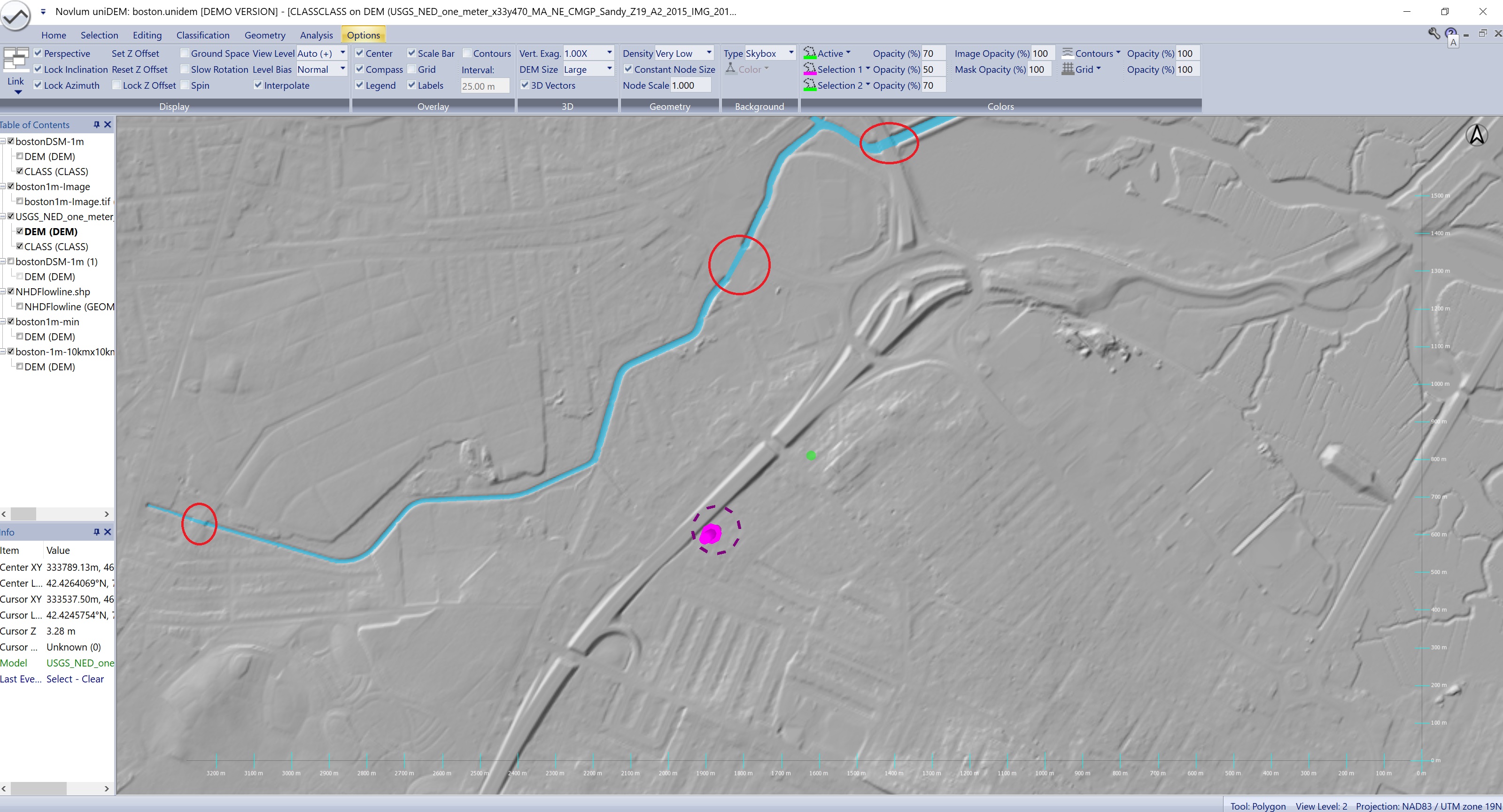
Edit drainage across bridges
Drainage monotonically edited
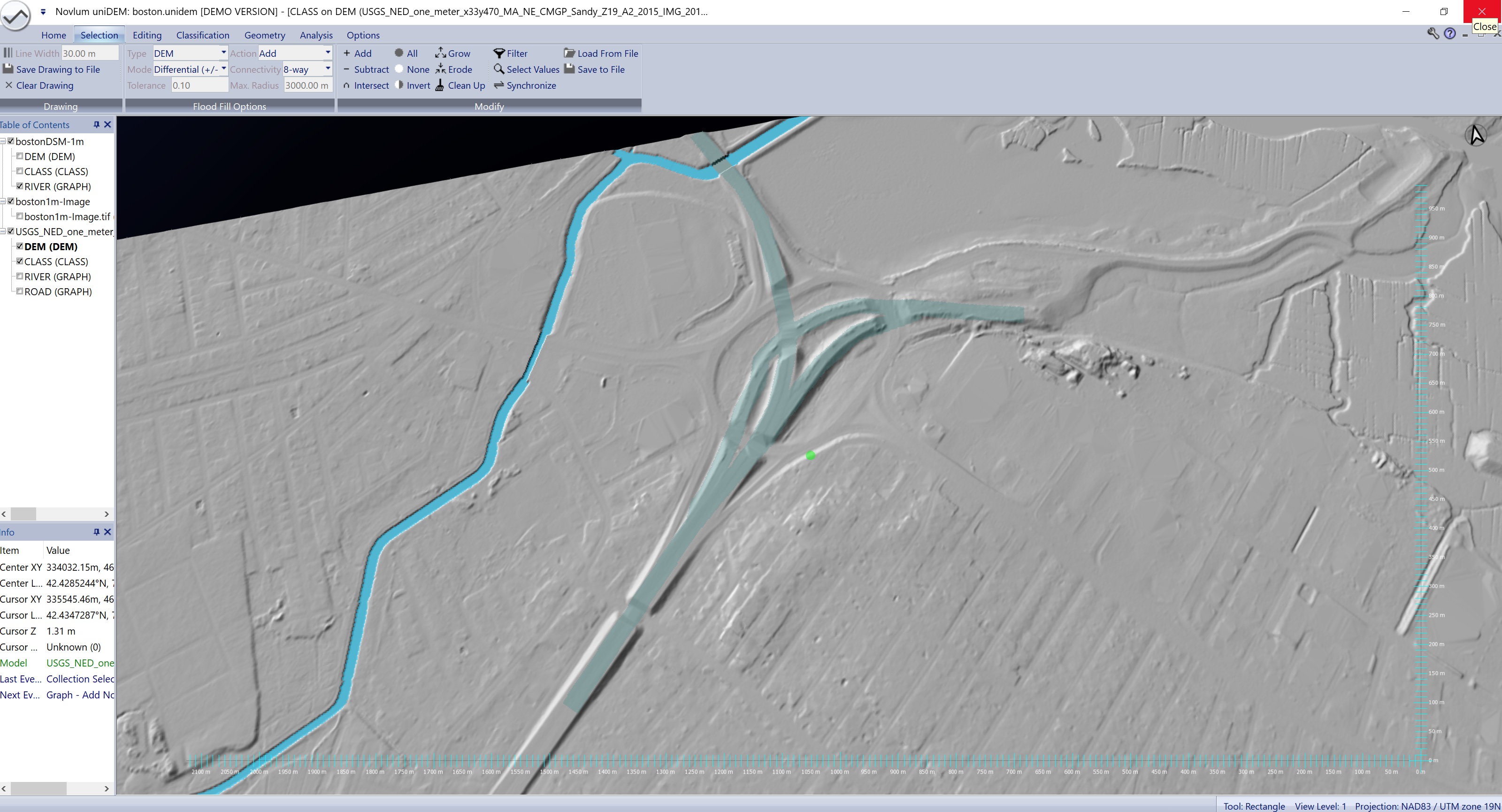
Roadway classified
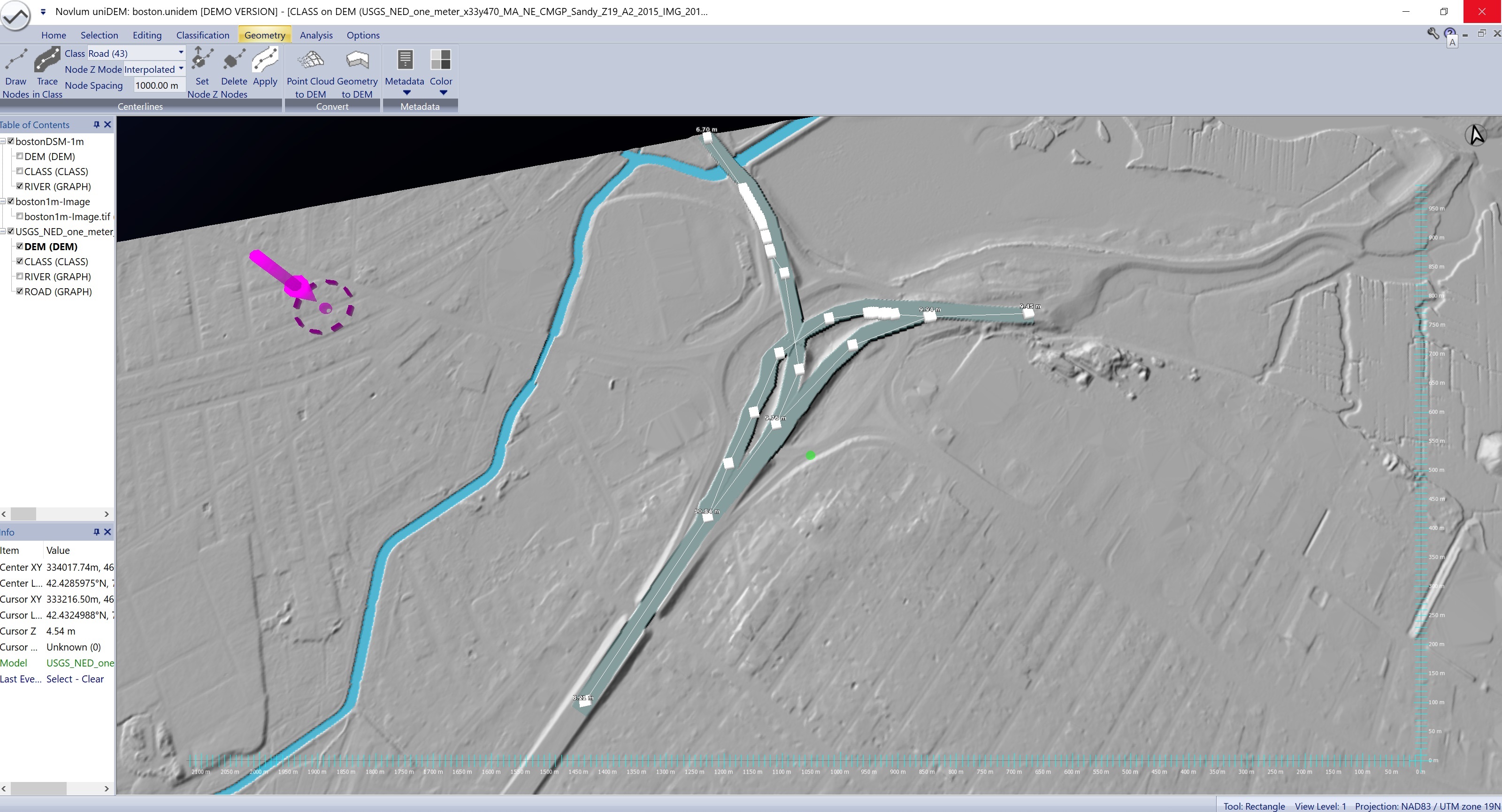
Roadways flattened and bridge decks added