Introduction To uniDEM
This tutorial is a brief introduction describing how to install and use uniDEM.
It includes the description of how to load and view an elevation model in uniDEM,
and ancillary data overlays to the elevation model and how to zoom/pan and toggle between 2D and 3D views.
The sample data used in this lesson is a Digital Terrain Model with a pixel spacing of 1 arc-second (30 meters) -
called NakedEarth - a 1° x 1 ° geotile covering Seattle, WA, USA.
Prior to commencing this lesson, please download the sample DTM and ancillary data:
- Download Sample Data: Sample_N47W123 (size: 260MB)
- Unzip the contents to a working folder
1. Install and Open uniDEM
Install uniDEM using one of two options:
Open uniDEM
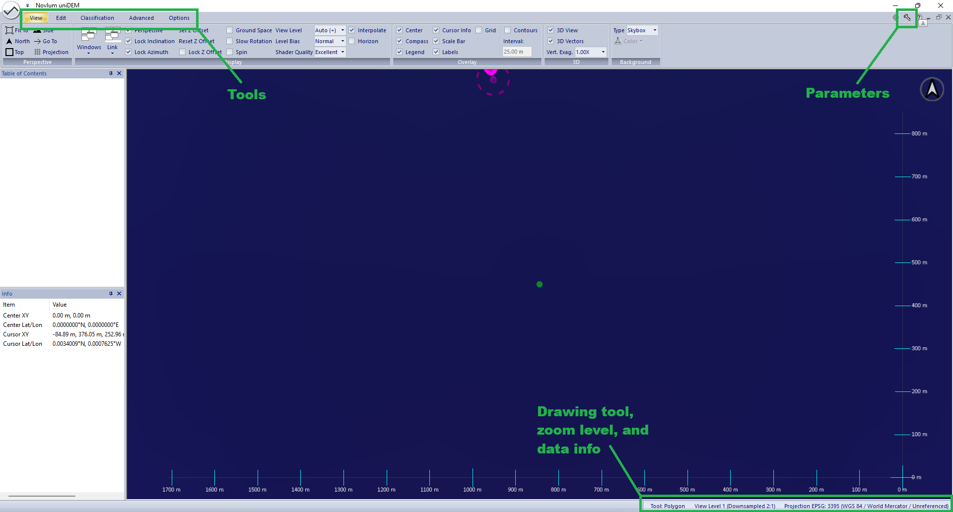
Start uniDEM. The blank uniDEM graphical interface appears with its default settings:
Help references:
Window Overview
2. Load a DEM
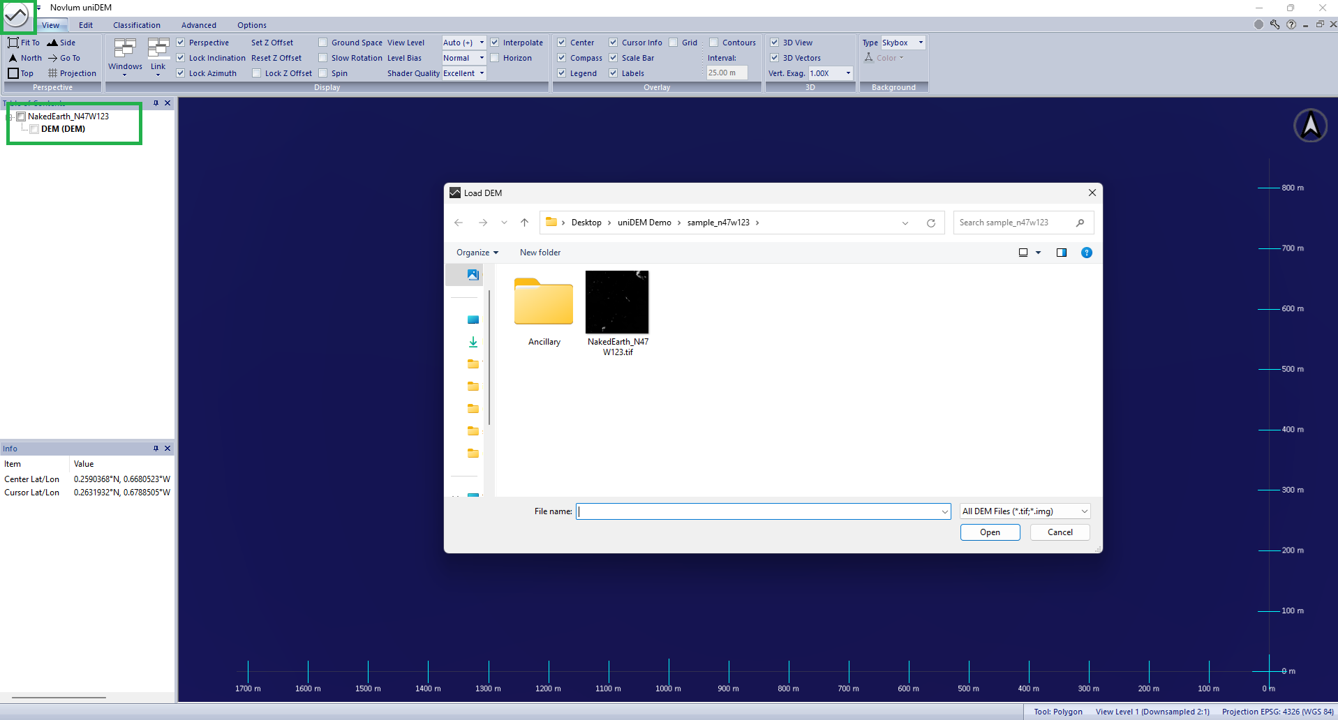
Load NakedEarth_N47W123.tif from the unzipped sample data by selecting uniDEMlogo → Load DEM and select NakedEarth_N47W123.tif.
The NakedEarth Digital Terrain Model (DTM) used in this sample is a 30 meter (1-arcsecond) elevation model automatically derived from
AW3D30.
Help references:
Load DEM |
Data Management |
Table of Contents
3. View the DEM
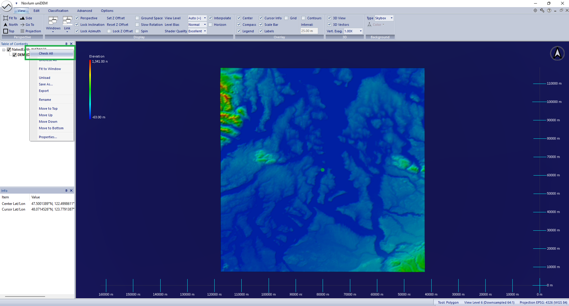
- Right click NakedEarth_N47W123 in the Table of Contents (TOC) on the left and select Check All
- The DEM will be displayed in the data view window
Note: DEM (DEM) in the dataset listed in the Table of Contents is bold. This means it is the Active Dataset.
The Active Dataset holds the DEM that will be edited.
When complete, uniDEM should display a colorized shaded relief of the DEM looking from the top down (Bird's-Eye View):
Help references:
Table of Contents |
Data Views
4. Interact with the DEM
This section shows how to interact with the data in 2D and 3D.
Pan and Zoom
- Click into Data View
- Pan: left click while moving mouse over the window
- Zoom: scroll with the mouse wheel
Rotate and Tilt
- Click into Data View
- Rotate: right click and move mouse left/right
- Tilt: right click and move mouse up/down
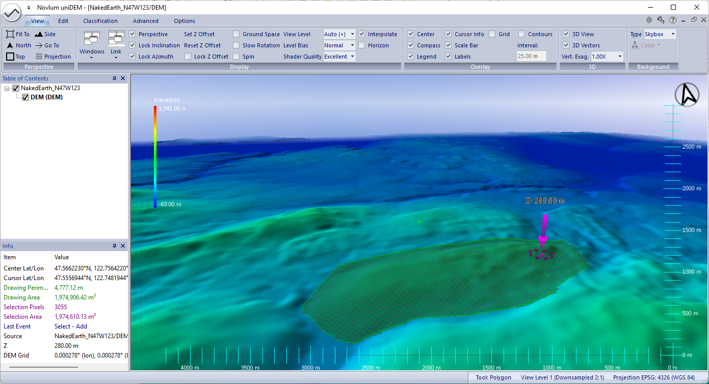
Make a Selection
Selections are the first step to editing DEM data. Selections can be performed on any loaded dataset
and edits are then applied within the Active Dataset.
- Select All
- Press Crtl-A to select the whole dataset
- Press Esc to clear the selection
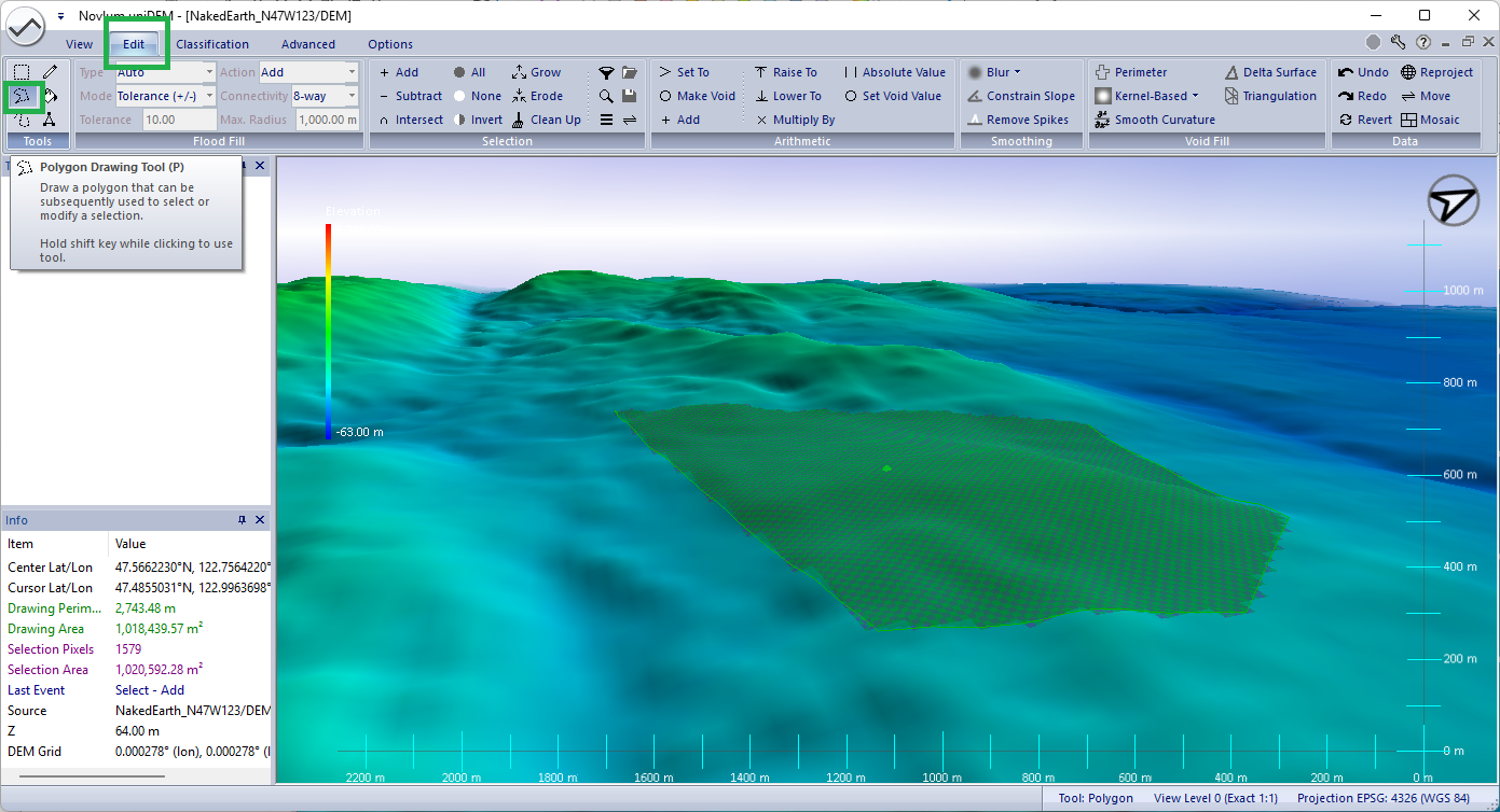
- Collect a Polygon
- Press P to enable the Polygon collection tool
- Hold down Shift+Left-Click key and left click a location over the DEM
- Click more points and a polygon will be drawn
- Press Shift+Backspace and the last point drawn will be removed
- Press Shift+'+' to add or Shift+'-' to remove the polygon drawing to the selection mask
- Press Shift+Esc to clear the polygon only, or Esc to clear both the polygon and the selection mask
There are many selection methods available including Flood filling, vector to raster and filtering techniques.
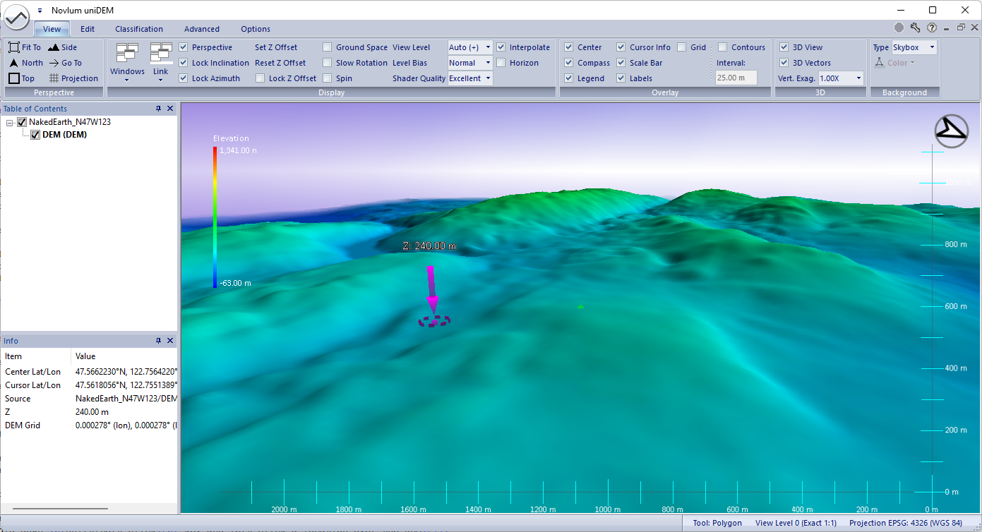
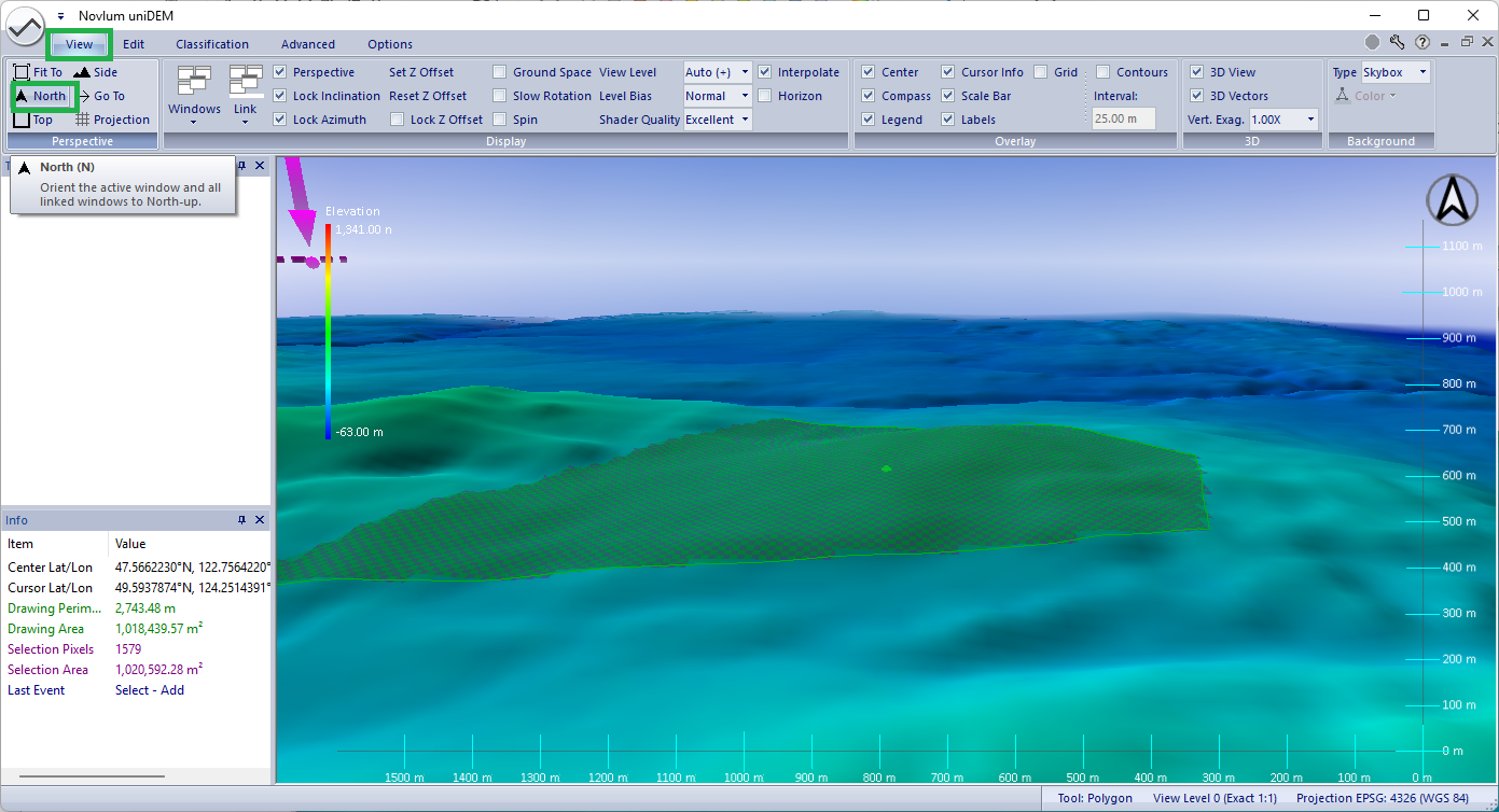
Change Viewing Orientation
- North-up: Press N
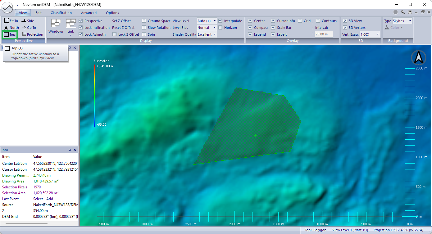
- Top-Down: Press T
- 2D (Orthographic): Press 2
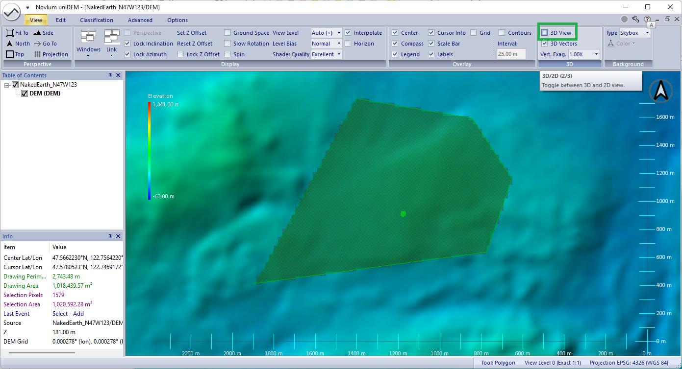
- 3D: Press 3

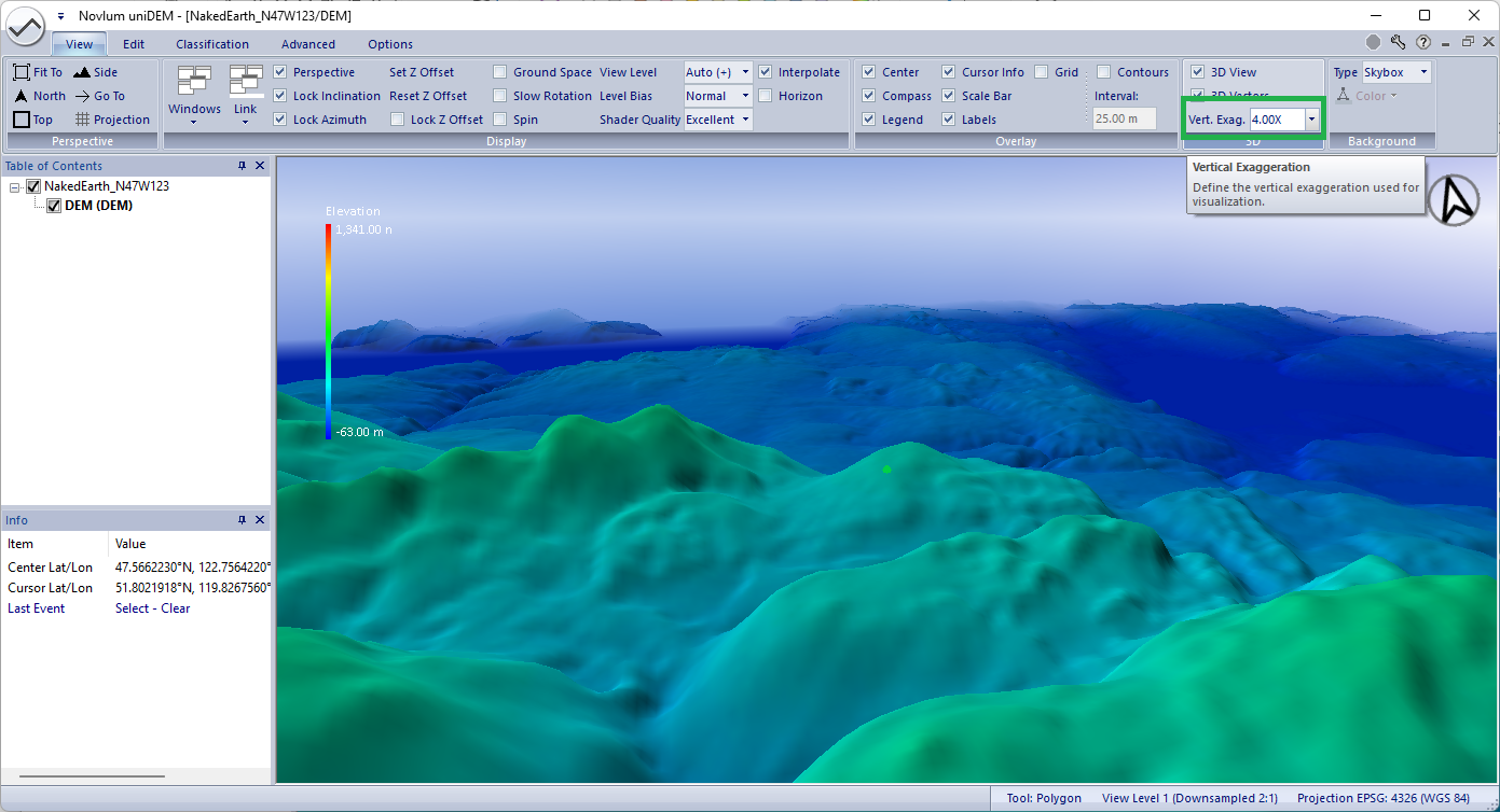
Vertical Exaggeration
To view the terrain in 3D it might be helpful to display the elevation model vertically exaggerated.
uniDEM offers the following exaggeration factors: 1x, 2x, 4x, 8x, 16x, 32x
- Within the View tab in the 3D panel, click Vert. Exag. and select the desired exaggeration factor
Help references:
Drawing Tools |
View |
Select All (Ctrl-A) |
Clear Selection (Esc) |
3D Viewing Options
5. Coordinates and Pixel Values
Coordinates
In the
Info Box the following (decimal) coordinates are shown:
- Center Lat/Lon: coordinate of the green center point of the window
- Cursor Lat/Lon: coordinate of the cursor position
- Drawing Perimeter: The perimeter of any polygon selection
- Drawing Area: area of any polygon selection
- Last/Next Event: previous and next tool execution event
- Source: data source dem under the cursor
- Z: elevation of the dem under the cursor
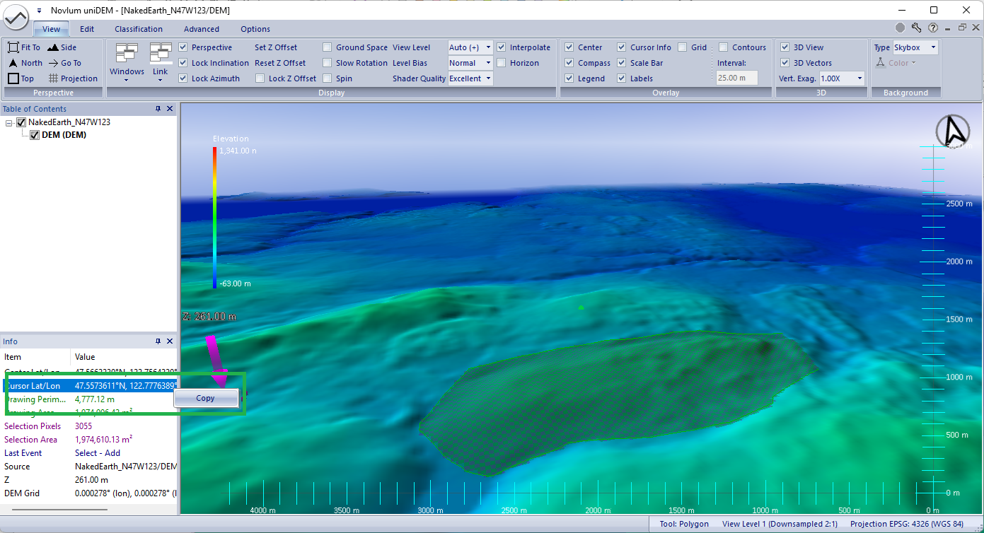
Geographic coordinates can be copied and paste into e.g. a document or the search field of any web-based map service:
- Right click on the coordinate
- Left click on the pop-up window "copy"
- Press Ctrl-V to paste the coordinate in the desired application
Help references:
Info Box
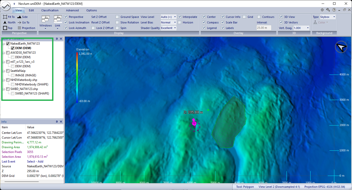
6. Load Ancillary Data
Additional data can be loaded in the form of imagery or shapefile geometries.
| Data Type |
Instruction |
| DEMs |
- Click uniDEM logo → Load DEM
- Within the demo directories navigate to: "\Ancillary\Elevation\"
- Select AW3D30_N47W123.tif and n47_w123_1arc_v3.tif
|
| Imagery |
- Click uniDEM logo → Load Image
- Within the demo directories navigate to: "\Ancillary\Imagery\"
- Select SeattleNaip.tif
|
| Shape file |
- Click uniDEM logo → Load Shapes
- Within the demo directories navigate to: "\Ancillary\Geometry\"
- Select NHDWaterbody.shp and SWBD_N47W123.shp
|
Help references:
Load DEM |
Load Image |
Load Mask |
Load Shapes
7. Display Multiple Views
The datasets can be viewed in multiple data views simultaneously.
The views can be linked so they move together or unlinked allowing for multiple zoom and view settings.
- Press Ctrl-N 3 times to create a total of four data views
- Press Ctrl-T to tile (organize) the data views
- Click top right data view
- Right click the AW3D30_N47W123 dataset in the TOC and click Check All
- Right click the SWBD_N47W123 dataset in the TOC and click Check All
- Click bottom left data view
- Right click the n47_w123_1arc_v3 dataset in the TOC and click Check All
- Right click the NHDWaterbody dataset in the TOC and click Check All
- Click bottom right data view
- Right click the NakedEarth_N47W123 dataset in the TOC and click Check All
- Right click the SeattleNaip dataset in the TOC and click Check All
- Right click the SeattleNaip dataset in the TOC and click Fit To Window
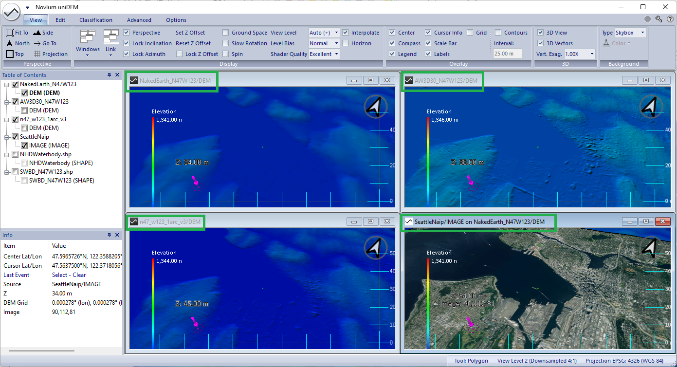
Note: The layer NakedEarth_N47W123 named DEM (DEM) listed in the Table of Contents is bold.
This means this is the Active Dataset. The active dataset holds the DEM that will be edited.
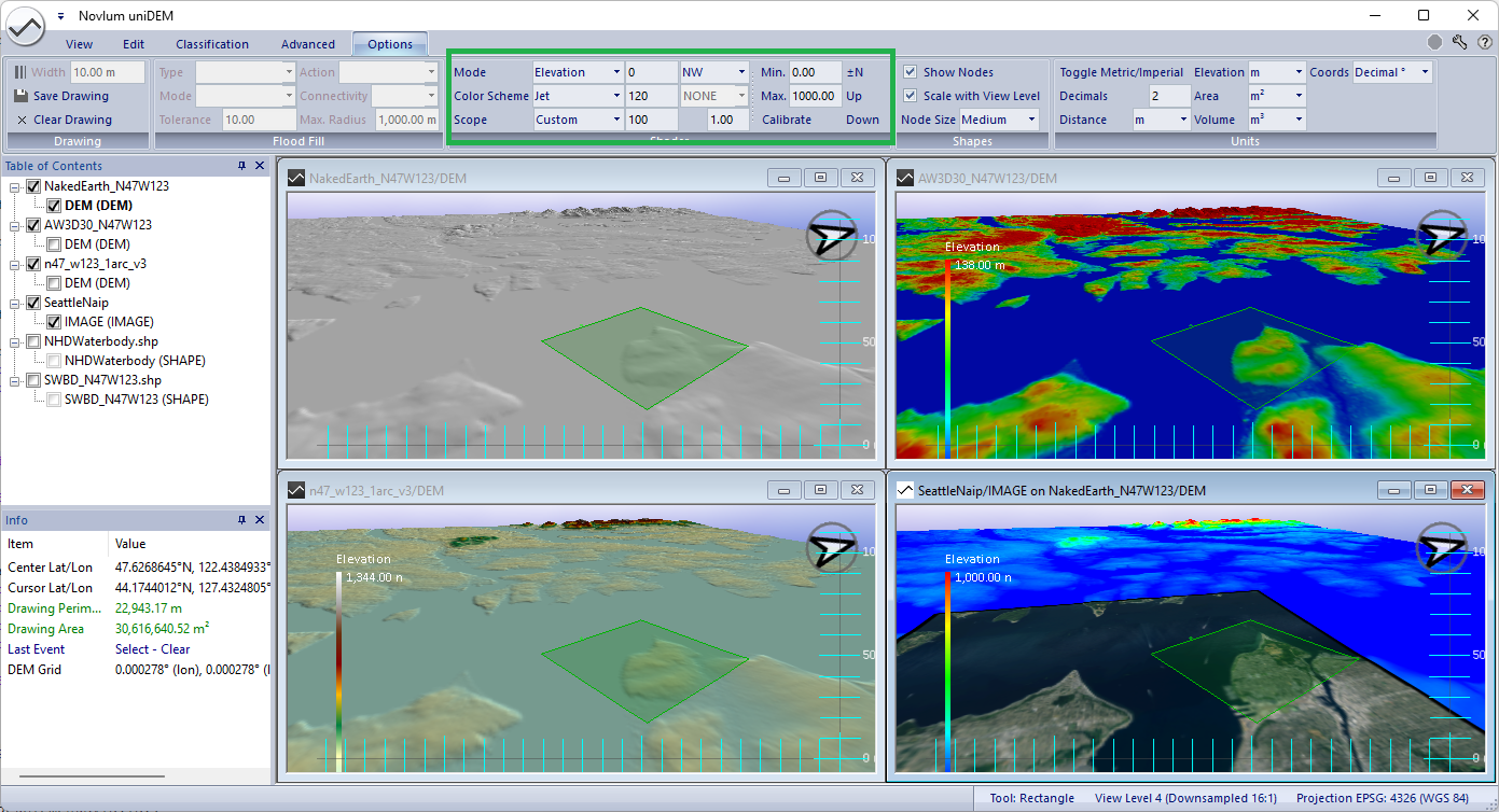
Adjust Data Views
uniDEM can present many different shaded relief colors.
By default DEM data is depicted as a colorized shaded relief with no vertical exaggeration.
- Click top left data view
- Press H to display the gray scaled shaded relief
- Within the Options tab in the Shader panel, adjust Sensitivity to 3.0 to "sharpen" the shaded relief
- Click top right data view
- Press R and draw a rectangle by using Shift + Left click
- Press B to calibrate the elevation range of the shaded relief to the range of elevations within the rectangle
- Click bottom left data view
- Within the Options tab in the Shader panel, change the Color Scheme from Jet to Topo
- Press B to calibrate the elevation range of the shaded relief to the range of elevations within the rectangle
- Click bottom right data view
- Within the Options tab in the Shader panel, change the Scope from Global to Custom
- Set Min. to 0
- Set Max. to 120
Help references:
Link Windows |
Shader |
Display |
3D Options